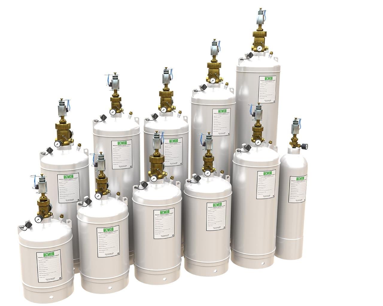


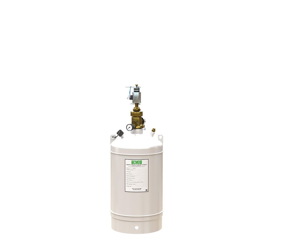
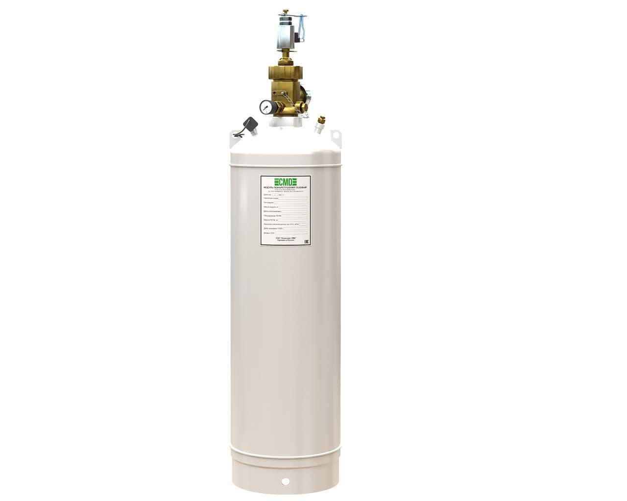
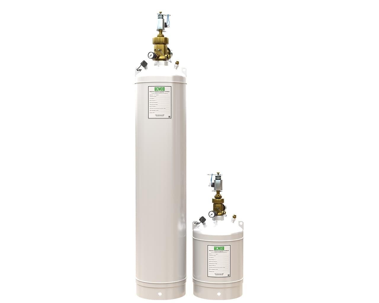
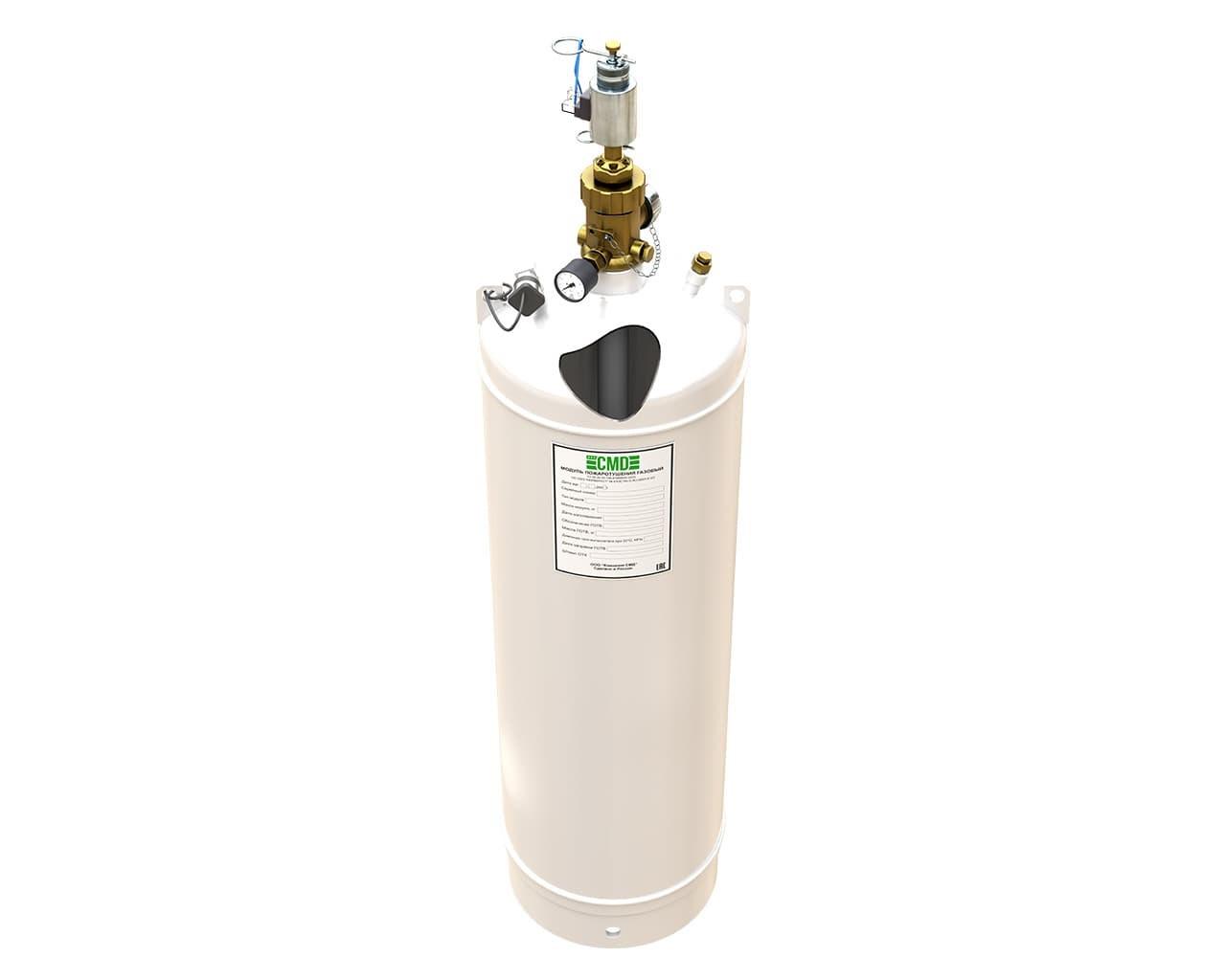
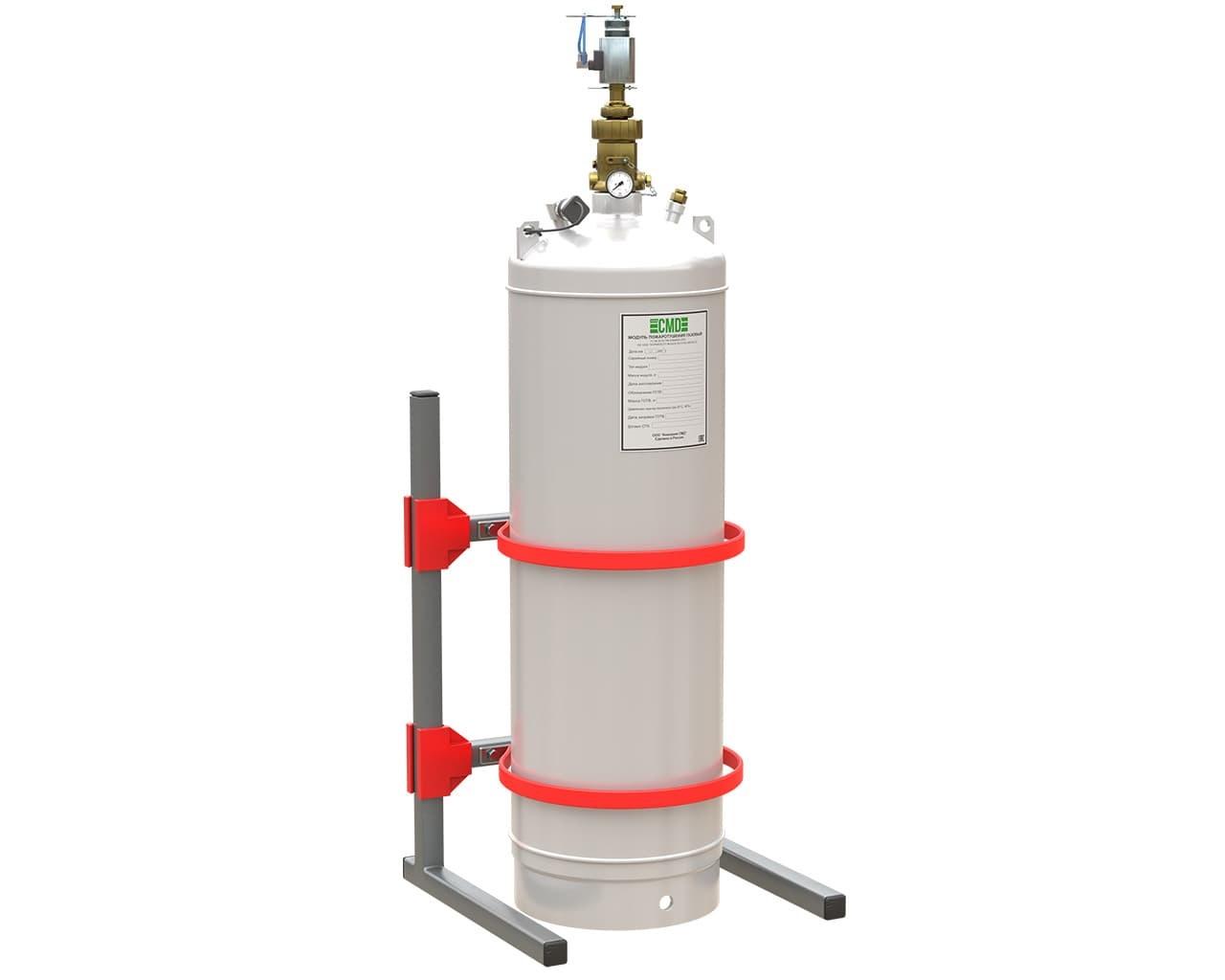
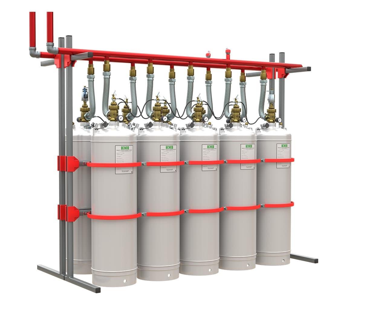
Automatic gas fire extinguishing modules and batteries, models: MPGT - 40 "SMD" (65-40-32), MPGT - 50 "SMD" (65-50-32), MPGT - 60 "SMD" (65-60-32), MPGT - 70 "SMD" (65-70-32), MPGT - 80 "SMD" (65-80-32), MPGT - 90 "SMD" (65-90-32), MPGT - 100 "SMD" (65-100-32), MPGT - 120 "SMD" (65-120-32), MPGT - 80 "SMD" (65-80-50), MPGT - 100 "SMD" (65-100-50), MPGT - 120 "SMD" (65-120-50), MPGT - 140 "SMD" (65-140-50), MPGT - 150 "SMD" (65-150-50) (hereinafter referred to as modules), as well as batteries that include identical MPGT modules and are connected by a common collector (hereinafter referred to as batteries).
Based on their storage method, fire extinguishing agents are classified as modular or centralized (a group of modules assembled into a battery and connected to a common manifold). Modules and batteries are components of automatic fire extinguishing systems and are used to store fire extinguishing agents for subsequent automatic, remote, or local activation in the event of fires in Classes A, B, and E electrical equipment with a voltage not exceeding the permissible voltage for the gaseous fire extinguishing agent.
The modules and batteries are operated and functional at ambient temperatures from minus 20°C to plus 50°C, climate type UHL (NF) category 4, atmosphere type II, III according to GOST 15150-69.
Modules and batteries are manufactured in accordance with the requirements of these technical conditions TU 26.30.50-771-81888935-2023 "Automatic gas fire extinguishing modules and batteries", TR EAEU 043/2017 "On requirements for fire safety and fire extinguishing equipment", SP 485.1311500.2020, GOST R 53281-2009, GOST 12.2.003-91, GOST 12.2.007.0-75, GOST 12.3.046-91, GOST 15150-69 vessels used for storing GFFS must meet the requirements of TR CU 032/2013 Technical Regulations of the Customs Union "On the safety of equipment operating under excess pressure" according to design documentation approved in the established in order.
The modules are designed for long-term storage and release of gaseous fire extinguishing agent in the event of a fire in a building (room) or structure.
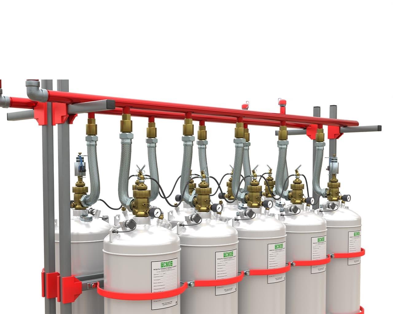
A group of modules, combined into a single battery, is designed for centralized storage of a large volume of fire extinguishing agents with subsequent release of fire extinguishing agents in the event of a fire in large areas.
The modules are used to extinguish class A, B and E fires in electrical equipment that is energized (the voltage at which fires can be extinguished without disconnecting the protected equipment must comply with the requirements of the regulatory documents for fire extinguishing equipment).
The storage method for flammable liquids is modular or centralized.
The batteries have the ability to be connected to a single pipeline manifold, forming a centralized storage point for flammable liquids.
Modules and batteries are used for fire protection of premises and equipment in a modular design for volumetric or local-volume fire extinguishing.
Modules and batteries are classified as refurbished and serviceable technical products.
The design of the modules and batteries meets the seismic resistance requirements of GOST 30546.1-98, GOST 30546.2-98 and GOST 30546.3-98 and has a performance of 9 points on the MSK-64 scale.
Service life from the date of manufacture is more than 30 years, extended upon re-examination.
| Module parameters |
Module type |
| MPGT - 40 "SMD" (65-40-32), MPGT - 50 "SMD" (65-50-32), MPGT - 60 "SMD" (65-60-32), MPGT - 70 "SMD" (65-70-32), MPGT - 80 "SMD" (65-80-32), MPGT - 90 "SMD" (65-90-32), MPGT - 100 "SMD" (65-100-32), MPGT - 120 "SMD" (65-120-32), MPGT - 80 "SMD" (65-80-50), MPGT - 100 "SMD" (65-100-50), MPGT - 120 "SMD" (65-120-50), MPGT - 140 "SMD" (65-140-50), MPGT - 150 “SMD” (65-150-50). |
|
| Working pressure MPa (kgf/ cm2 ) |
6.5 (65) |
| Test pressure, MPa (kgf/ cm2 ) |
9.75 (97.5) |
| Displacement gas pressure, MPa (kgf/ cm2 ) |
4.2 (42) |
| Operating pressure of the membrane safety device, MPa |
9± 0.45 |
| Time to release 95% of the flammable liquid by weight, s, no more than |
10 |
| Residue of GOVT, no more than % of the mass of GOVT |
0.5 |
| Conditional passage of the ZPU |
DN32 or DN50 |
| Operating temperature, °C |
minus 20 °C to plus 50 °C |
| Service life until first re-inspection, years |
15 |
| Resource of operations, not less than, times |
10 |
| Service life of the module, years, not less than |
30 |
| The mode of operation of the starting device |
electromagnetic, pneumatic, manual |
| Manual start-up force of the PU, N |
no more than 150 |
| Solenoid supply voltage, V |
24±2 |
| Current consumed by the solenoid, A, no more than |
1.5±0.2 |
| Pulse duration, s, no more than |
2 |
| Pneumatic actuator response pressure, MPa (kgf/ cm2 ) |
0.8 (8) |
| Maximum filling factor, kg/l |
1.1 (Freon-227ea), 0.9 (Freon-125), 1.2 (FK-5-1-12) |
| Current for checking the PU circuits, A, no more than |
0.5 |
Overall dimensions of the module with a nominal bore shut-off and starting device DN32
| Module parameters |
Module type |
|||||||
| MPGT - 40 “SMD” (65-40-32) | MPGT - 50 “SMD” (65-50-32) | MPGT – 60 “SMD” (65-60-32) | MPGT - 70 " SMD" (65-70-32) | MPGT - 80 “SMD” (65-80-32) | MPGT - 90 “SMD” (65-90-32) | MPGT - 100 “SMD” (65-100-32) | MPGT - 120 “SMD” (65-120-32) | |
| Module capacity, l. | 40 | 50 | 60 | 70 | 80 | 90 | 100 | 120 |
| Type of ZPU |
QRF 32/6.7 |
|||||||
| Nominal bore diameter of the valve, mm |
32 |
|||||||
| Equivalent length, m, no more than |
2.3 |
|||||||
| Connecting thread of the outlet fitting of the ZPU |
M48x2 |
|||||||
| External diameter of the module (cylinder), D, mm |
373±1.5 |
|||||||
| Cylinder neck thread, mm |
PZ56 |
|||||||
| Height, L*, mm | 762±10 | 862±10 | 962±10 | 1062±10 | 1162±10 | 1262±10 | 1362±10 | 1562±10 |
| Height to the center of the outlet, L 1 , mm | 662±10 | 762±10 | 862±10 | 962±10 | 1062±10 | 1162±10 | 1262±10 | 1462±10 |
| Weight of empty module, kg** | 59.7±2 | 66.7±2 | 70.6±2 | 81.7±2 | 89.2±2 | 96.7±2 | 105.2±2 | 119.2±2 |
Note:
* - without starting device;
** - without packaging, protective cap and starting device.
The type of ZPU is determined when ordering.
Overall dimensions of the module with a nominal bore shut-off and starting device DN50
">140
| Module parameters | Module type | ||||
| MPGT - 80 “SMD” (65-80-50) | MPGT - 100 “SMD” (65-100-50) | MPGT - 120 “SMD” (65-120-50) | MPGT - 140 “SMD” (65-140-50) | MPGT - 150 “SMD” (65-150-50) | |
| Module capacity, l. | 80 | 100 | 120 | 150 | |
| Type of ZPU |
QRF 50/6.7 |
||||
| Nominal bore diameter of the valve, mm |
50 |
||||
| Equivalent length, m, no more than |
3.7 |
||||
| Connecting thread of the outlet fitting of the ZPU |
M68x2 |
||||
| External diameter of the module (cylinder), D, mm |
373±1.5 |
||||
| Cylinder neck thread, mm |
M80x2 |
||||
| Height, L*, mm |
1205±10 |
1405±10 | 1605±10 | 1805±10 |
1905±10 |
| Height to the center of the outlet, L 1 , mm |
1076±10 |
1276±10 | 1476±10 | 1676±10 |
1776±10 |
| Weight of empty module, kg** |
98.5±2 |
113.9±2 | 129.4±2 | 145±2 |
152±2 |
Note:
* - without starting device;
** - without packaging, protective cap and starting device.
The type of ZPU is determined when ordering.
The structure of the module symbol must meet the following requirements:
| MPGT - | XXX | " XXX " | ( XX - | XX - | XX ) |
| 1 | 2 | 3 | 4 | 5 | 6 |
Example of designation of a gas fire extinguishing module:
MPGT-150 “SMD” (65-150-50)
The structure of the battery symbol must meet the following requirements:
center;" width="60">2
| ХБХХ – | MPGT | XXX | " XXX " | ( XX - | XX X ) |
| 1 | 3 | 4 | 5 | 6 |
Example of designation of a gas fire extinguishing module:
| 2B10 – | MPGT | 150 | SMD | ( 65 - | 1500 ) |
| 1 | 2 | 3 | 4 | 5 | 6 |
EAEU RU C-RU.AB03.B.00299/23. Certificate of Conformity with EAEU TR 043/2017 "On Requirements for Fire Safety and Fire Extinguishing Equipment" EAEU RU C-CN.NE55.B.00089/25. Certificate of Conformity with EAEU TR 043/2017 "On Requirements for Fire Safety and Fire Extinguishing Equipment" EAEU RU C-CN.NE55.B.00090/25. Certificate of Conformity with EAEU TR 043/2017 "On Requirements for Fire Safety and Fire Extinguishing Equipment" Operation manual combined with the passport. Automatic gas fire extinguishing modules and batteries, models: MPGT - 40 "SMD" (65-40-32), MPGT - 50 "SMD" (65-50-32), MPGT - 60 "SMD" (65-60-32), MPGT - 70 "SMD" (65-70-32), MPGT - 80 "SMD" (65-80-3 AUGPT Questionnaire