| Explosion protection marking | «1Ex d IIB T6 Gb» | |||
| Ingress protection | IP67 | |||
| Operating temperature range | -60 .. +60°С | |||
| Number of cable glands (sides А, С and В, D), max. | ||||
| sides А,С (large) | sides B, D (small) | |||
| KVMK -type V2 | 12 | 9 | ||
| KVMK -type G2 | 15 | 9 | ||
| KVMK -type D2 | 45 | 25 | ||
| KVMK -type E2 | 60 | 36 | ||
| Overall dimensions without cable glands | Internal space if measured by wiring board | Mounting dimensions | Enclosure weight, max | |
| KVMK -type V2 | 290х250х172mm | 200х150х123mm | 160х245mm | 14kg |
| KVMK -type G2 | 421х322х248mm | 313х223х198mm | 300х294mm | 23kg |
| KVMK -type D2 | 568х368х257mm | 442х270х205mm | 360х343mm | 45kg |
| KVMK -type E2 | 670х470х362mm | 545х350х298mm | 500х437mm | 65kg |
| Connected voltage, max. | 600V | |||
| Enclosure material | aluminium alloy | |||
Example of order information:
KVMK–type V2 Ex –А[(x1-vh1-vh2-…), (x2 -vh3-…),…] –B[(x3-vh4-…)] –C[…] –D[…] –XT[n1(s1), n2(PEs2) –w]
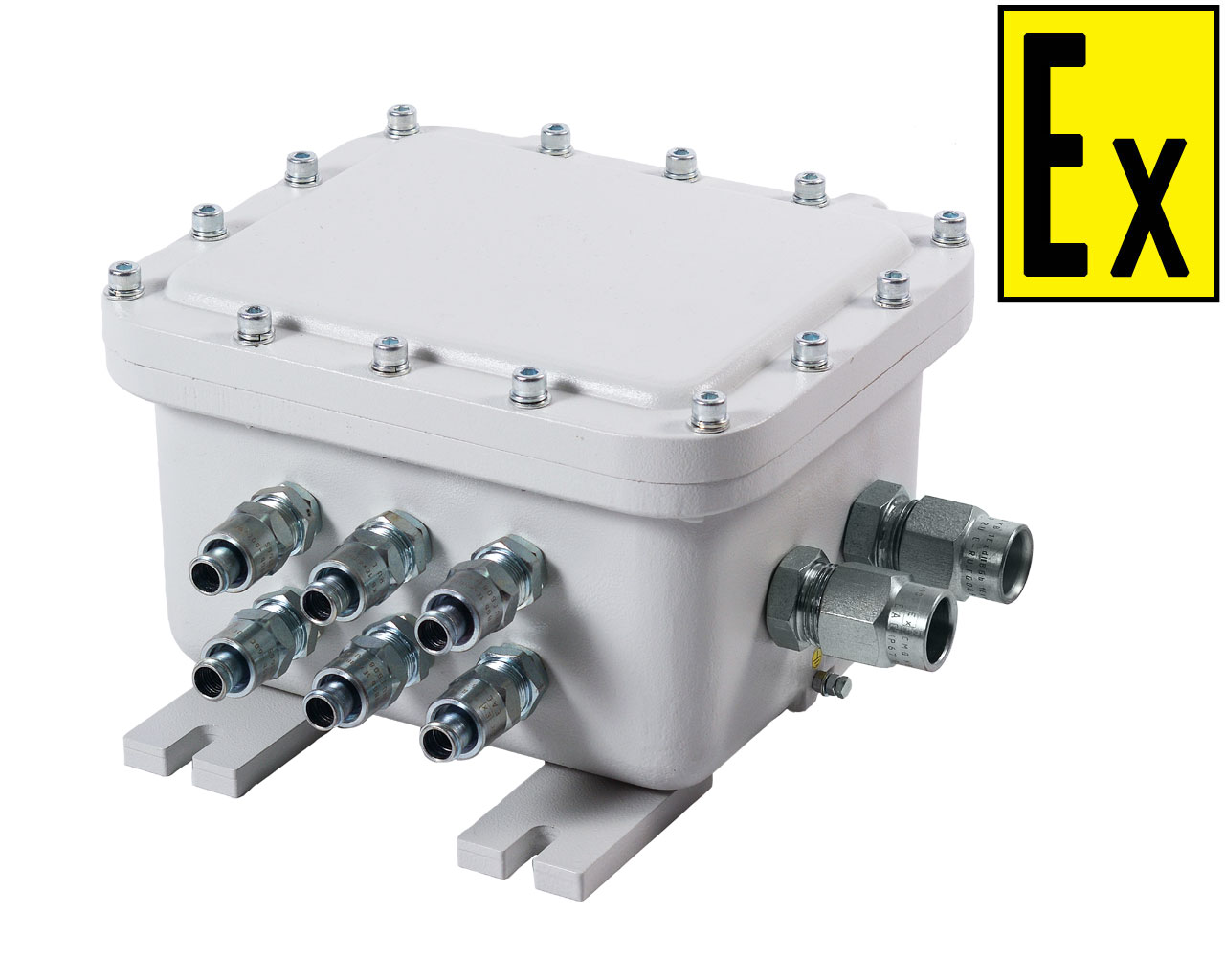
1 – box type and explosion protection marking:
KVMK - type V2 1ExdIIBT5Gb, KVMK - type G2 1ExdIIBT5Gb, KVMK - type D2 1ExdIIBT5Gb, KVMK - type Е2 1ExdIIBT5Gb;
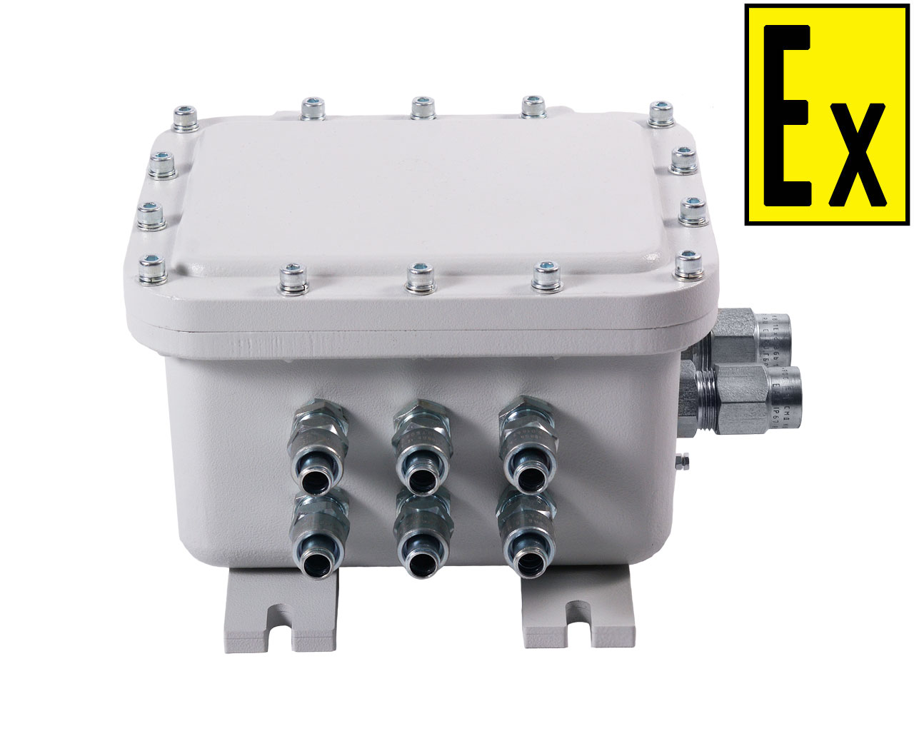
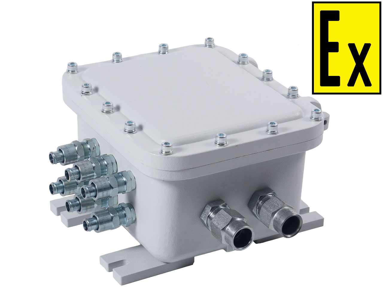
2 – type, number and positions of cable glands:
"А" "С" - marker for section with description of large sides A and C of the box;
“B”, “D” – marker for section with description of small sides B and D of the box;
x1, x2 … x3– cable gland types (https://smd-tlt.ru/eng/40 ):
G1/2K, G3/4K, G1K – for cable of diameter 6-12 mm, 10-18 mm, 18-25 mm surface routing;
G1/2B, G3/4B, G1B – for armoured cable of drift diameter 6-12 mm, 10-18 mm, 18-25 mm;
G1/2T1/2 – for routing 8-12 mm cable in pipe with G1/2 connection thread;
G1/2T3/4, G3/4Т3/4 – for routing 10-18 mm cable in pipe with G3/4 connection thread;
G1Т1 – for routing 18-25 mm cable in pipe with G1 connection thread;
G1/2KM15, G1/2KM20, G3/4KM20, G3/4KM25, G3/4KM32, G1KM32, G1KM38 – for routing the cable in 15 mm, 20 mm, 25 mm, 32 mm and 38 mm metal hose respectively.
vh1, vh2… - coordinate of the cable gland position in the following format:
v – vertical position symbol (a, b, c);
h – horizontal position number (1, 2, …).
3 – type and number of terminal clamps:
“ХТ” – marker for section with description of the screw terminal clamps.
“PE” – marker for section with description of the screw terminal clamps for earthing.
n1, n2… – multiplier for number of terminal clamps of certain type.
s1, s2 – max. wire gauge for terminal clamp (2.5mm2, 4mm2, 10mm2, 16mm2, 35mm2, 70mm2).
w – designation for position of the terminal clamps:
“a1” – along the long side А in one row; “a2” – along the long side А in two rows;
“b1” – along the short side B in one row; “b2” – along the short side B in two rows.
Example of order information:
«KVMK type V2 1ExdIIBT5Gb– А[(G1/2Т1/2-a1-a5-b3), (G1/2К-b5)] – B[(G3/4Т3/4-b2)] – C[(G1/2Б-a3-b3)] – ХТ[10(2.5), 2(PE4) – a1]»:
junction box with explosion protection marking «1Ex d IIB T5 Gb»;
on the side А:
three cable glands for routing 8-12 mm cable in pipe with G1/2 connection thread
in positions a1, a5, b3;
one cable gland for cable of diameter 6-12 mm surface routing in position b5;
on the side В:
one cable gland for routing 10-18 mm cable in pipe with G3/4 connection thread in position b2;
on the side C:
two cable glands for routing 8-12 mm cable in pipe with G1/2 connection thread in positions a3 и b3;
terminal clamps:
10 pieces for wire with a maximum cross section of 2.5 mm 2;
2 pieces for wire with a maximum cross section of 4.5 mm;
designation for position of the terminal clamps – а1.